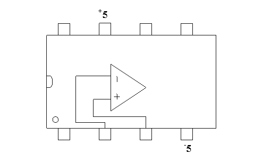
Apparatus
breadboard
741 or 411 operational
amplifier speaker
oscilloscope
function generator
various
resistors digital multimeter
Procedure


1. Measure the gain of your amplifier to two significant digits, using the voltage cursors on the oscilloscope. Note whether or not the signal is inverted.
2. Repeat this gain measurement at the following frequencies: 10 kHz, 100 kHz, 1 MHz, and 10 MHz.
3. Go back to 1 kHz and change the input waveform amplitude to 1 volt. What happens to the output?
4. Test out your amplifier with a 1 kOhm feedback resistor
and a 100 Ohm input resistor, using as input a 1 kHz wave with 0.1V
amplitude.
Determine the output and input voltage as before.
5. Finally, add a second resistor to the circuit as follows:

where R1 = 100 Ohm, Rf = 1 kOhm, and R2 = 50 Ohm. Feed
the
output of the circuit to both an oscilloscope and a speaker. Set
your input amplitude to 0.01 V, increase it by 0.01 V until the output
starts to "clip." What does this sound like before and after the
output "clips"?
When you are done, please turn off the breadboard and measure the resistances of your resistors with the DMM, while they are unplugged from the circuit.
Analysis
1. Create a table showing the gain of your amplifier circuit as a
function
of frequency and compare it to the expected theoretical value. Was the
output signal inverted? How did the gain change with frequency, or did
it?
2. How can you explain the output of the amplifier in part 3. above
(hint: think about the power supplies)? What does it sound like when
the output "clips"? Why?
3. How can you explain the input voltage in part 4. above (hint:
think
about
input resistance)?
4. How can you explain the sound before and after the voltage
"clips" in part 5?
Conclusion
Be sure to conclude with a statement regarding what you learned in
the lab.