Department of Physics, Bates College
Lewiston, ME 04240
Abstract
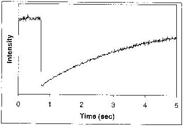
| We are studying the temporal behavior of a magneto-optical trapping apparatus allowing simultaneous cooling and trapping of Cs and Rb in a compact octagonal vapor cell. The background vapor pressures of each species are independently controllable, as are the intensities and frequencies of the respective trapping and repump lasers. Trap sizes and positions are determined by a pair of CCD cameras which view the trap from orthogonal directions. Separate photomultiplier tubes monitor fluorescence from the two species, permitting measurement of the fill time of each trap in the presence or absence of the other. The apparatus is easily modified for simultaneous trapping of the two Rb isotopes. |
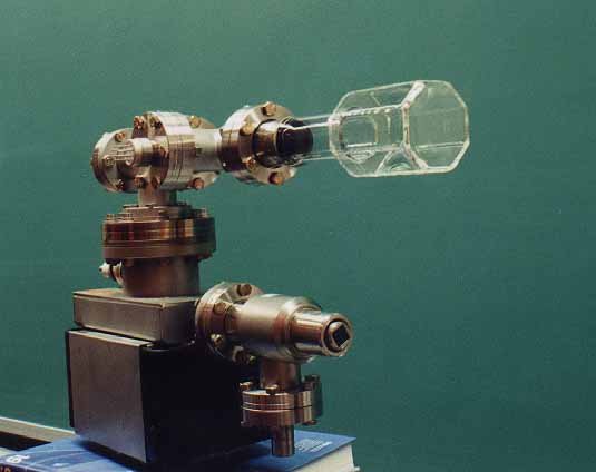
The Vapor Cell
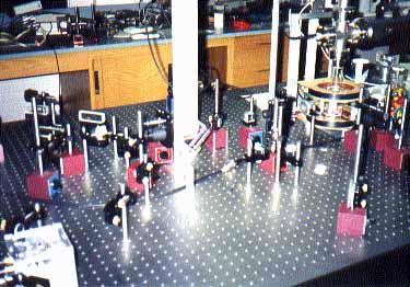
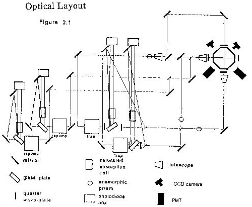
Optical Table
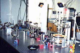
Another View